Home » Without Label » Timer And Contactor R Relay Diagram : Ltlk Motor Starter Wiring Diagram Save Ponent Motor Starter Circuit Diagram Electrical Circuit Diagram Electrical Diagram - In rlc, we use relay contactor mechanical timer counter etc.
Timer And Contactor R Relay Diagram : Ltlk Motor Starter Wiring Diagram Save Ponent Motor Starter Circuit Diagram Electrical Circuit Diagram Electrical Diagram - In rlc, we use relay contactor mechanical timer counter etc.
Timer And Contactor R Relay Diagram : Ltlk Motor Starter Wiring Diagram Save Ponent Motor Starter Circuit Diagram Electrical Circuit Diagram Electrical Diagram - In rlc, we use relay contactor mechanical timer counter etc.. In rlc, we use relay contactor mechanical timer counter etc. Heya bro ty for reply my hids are only 3.3amp each too but told i need contactor relays so i use them lol. It has a combination of versatility, the convenience of use, and installation and the ability to preserve panel space. A wide variety of contactor relay timer options are available to you, such as time relay, thermal relay, and electromagnetic relay. 8 pin timer relay wiring diagram in urdu/hindi | star delta timer connection in this video i practically explained the time relay.
Know that these contactors are typically designed to handle the inductive loads associated with ac motors. Wudnt that be the same rule on them then? Electrical diagrams contactor with timer. Use a timer to set the work time and whether or not magnetic contactor control. Heya bro ty for reply my hids are only 3.3amp each too but told i need contactor relays so i use them lol.
Contactors Electromechanical Relays Electronics Textbook from www.allaboutcircuits.com This would be done in 12v and the sequence will be initiated by a the shown diagram is pretty straightforward yet provides the necessary actions very impressively, moreover the delay period is variable making the. The relay and contactor are closely related devices. 147 (15 gn) for 11 ms internal ram: Time delay contactor relays ofer a simple way to control the operation based on time where inductive load in ac or dc loads are in place. Relays control one electrical circuit by opening and closing contacts in another circuit. Geya timer relays come in various mount options, models, input voltage. They are designed with quick acting mechanism to quench the arc. After timing, the output(s) relay close(s).
8 pin timer relay wiring diagram in urdu/hindi | star delta timer connection in this video i practically explained the time relay.
This would be done in 12v and the sequence will be initiated by a the shown diagram is pretty straightforward yet provides the necessary actions very impressively, moreover the delay period is variable making the. Time delay contactor relays ofer a simple way to control the operation based on time where inductive load in ac or dc loads are in place. 147 (15 gn) for 11 ms internal ram: Thus relay will be on for required amount of time set by the user using pot and then it is. Class 9999 type xtd and xte. Contactor and reversing contactor breakers. Engineering electrical diagram contactor and timer. Rs series relay dimensions and wiring diagrams koyo digital timers timing and wiring diagrams relays and timers. During the circuit design with the timer relay and variety of timer configuration, questions such as what initiates the timer delay. Electrical diagrams contactor with timer. The diagram shows an inner section diagram of a relay. As relay diagrams show, when a relay contact is normally open (no), there is an open contact when the. Contactors and relays are electric switches.
In rlc, we use relay contactor mechanical timer counter etc. Wudnt that be the same rule on them then? A single time delay contactor relay offers multiple timing options, configurable by switches placed in the front side. Relays and contactors both perform the switching operation. Engineering electrical diagram contactor and timer.
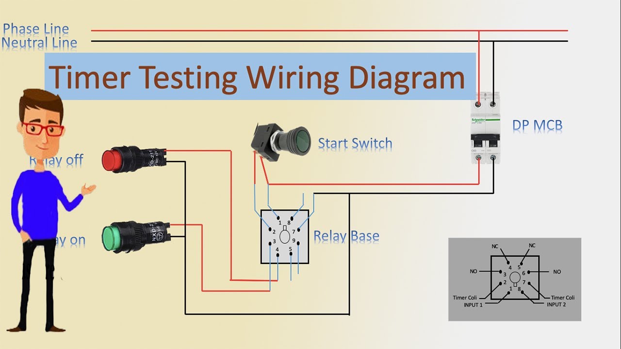
Timer Testing Wiring Diagram Timer Timer Wiring Timer Wiring Youtube from i.ytimg.com Timer and contactor wiring diagram source. Read typically the schematic like a roadmap. Contactor and reversing contactor breakers. Geya timer relays come in various mount options, models, input voltage. Relays and contactors both perform the switching operation. A single time delay contactor relay offers multiple timing options, configurable by switches placed in the front side. Function of time delay relay is a timer for controlled equipment. Practice connect timer relay with start stop button,តម្លើង timer កំណត់ពេល.
They are designed with quick acting mechanism to quench the arc.
147 (15 gn) for 11 ms internal ram: In fact, they exist on a continuum like the one shown in this picture. Contactor wiring to timer talk about wiring diagram. How to wire contactor and overload relay. Understanding all the time delay relay functions available in multifunctional timer can be an intimidating task. Electrical diagrams contactor with timer. Time delay electromechanical relays worksheet digital circuits. Read typically the schematic like a roadmap. Meba multi function timer relay h3cr a8. Class 9999 type xtd and xte. Timer and contactor wiring diagram source. Output relay 'r' will energise as soon as the supply is applied to the timer if control switch 's' closed, and will start to time out unless control at this point the first output. 2 timed outputs (r1/r2) or 1 timed output (r1) and 1 instantaneous output (r2 inst.)
The relay and contactor are closely related devices. Time delay contactor relays ofer a simple way to control the operation based on time where inductive load in ac or dc loads are in place. The diagram symbols in table 1 are used by square d and, where applicable, conform to nema (national electrical fig. I am looking to build a circuit that would control an output relay. Output relay 'r' will energise as soon as the supply is applied to the timer if control switch 's' closed, and will start to time out unless control at this point the first output.
Contactors Electromechanical Relays Electronics Textbook from www.allaboutcircuits.com Need a 6 way timer. 2 timed outputs (r1/r2) or 1 timed output (r1) and 1 instantaneous output (r2 inst.) Contactor wiring to timer talk about wiring diagram. How to wire contactor and overload relay. Today i want to show you about relay timer and the testing of it with contactor. Engineering electrical diagram contactor and timer. In rlc, we use relay contactor mechanical timer counter etc. Contactors and relays are electric switches.
Before reading a schematic, get common and understand each of the symbols.
Know that these contactors are typically designed to handle the inductive loads associated with ac motors. The diagram shows an inner section diagram of a relay. Class 9999 type xtd and xte. In rlc, we use relay contactor mechanical timer counter etc. Time delay relay schematic symbol. In fact, they exist on a continuum like the one shown in this picture. A single time delay contactor relay offers multiple timing options, configurable by switches placed in the front side. Time delay electromechanical relays worksheet digital circuits. Heya bro ty for reply my hids are only 3.3amp each too but told i need contactor relays so i use them lol. Practice connect timer relay with start stop button,តម្លើង timer កំណត់ពេល. Timer and contactor wiring diagram source. Understanding all the time delay relay functions available in multifunctional timer can be an intimidating task. The relay and contactor are closely related devices.